Now it’s time for the timer. When the switch is turned on, I want the pump to run for a couple of seconds and then turn off automatically. I want this behavior to prevent my balcony from getting flooded. In technical terms what I need is an edge triggered, non retriggerable monostable mutivibrator… aka – a timer. I was looking a bit at modern equivalents of the 74LS121, but they are a bit hard to find and they cannot drive very much current. So in the end I fell for the good old NE555. I guess a digital boy would have gone for a PIC-processor, but I am old school. I also know the NE555 is totally outdated, but it is easy to work with, easy to find and the output stage packs enough punch to drive a relay directly. I will be paying a price in form of high power consumption, but I had one lying around, so I took that. The NE555 can easily be connected as a monoflop, but it is not edge triggered so I have to fix that externally. The circuit I ended up with is shown below:
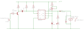
C1, R6 and R2 form the timing RC-circuit. It gives a max time around 7 seconds. D2 is a bit special, I read that it is needed to avoid the spike from the relay retriggering the circuit. I did not actually mount it on my board (I forgot it), but I put it in now when I made the schematic.
R3, C2, R4 makes the input edge triggered, as only flanks pass the capacitor.
I tried connecting the output from the receiver (the slaughtered spotlight) directly to the input, but the flank was not high enough, so I had to add R5, Q1 to amplify the signal. Below is the circuit tested on an experiment board.


No comments:
Post a Comment